Micro-ROS on Microcontrollers for Embedded Robot Nodes
Bridges the architectural gap between ROS 2 graphs and microcontroller hardware.
ROS 2 was built to solve problems in distributed, high-level computing: coordinating perception stacks, planners, and navigation modules across networked processes. It was never built to control hardware pins on a fixed timing schedule, so that gap is where micro-ROS has to start. The middleware that carries ROS 2 messages, whether DDS or Zenoh, handles process-to-process communication between nodes that assume a full operating system underneath them. Reading an encoder, driving a PWM signal, or sampling an IMU at a fixed rate demands a different kind of guarantee: a timing loop that closes in microseconds, not a message bus that routes between participants on a network. The ROS 2 design paper describes the system as a modular, distributed framework, and that framing is accurate. Modularity of that kind assumes a device with enough memory and processing headroom to run multiple concurrent processes, a DDS participant, and a scheduler capable of juggling them. A microcontroller with tens of kilobytes of RAM has none of that headroom to spare.
A survey that examines middleware along three structural dimensions finds that temporal predictability for control loops is a requirement that strains even capable, general-purpose hardware running ROS 2's existing middleware. On a microcontroller, that strain turns into an outright mismatch. The tasks that demand hard timing guarantees, sensor sampling, actuator control, safety interlocks, are routed to MCUs precisely because MCUs can deliver deterministic timing in a way a general-purpose Linux process cannot. That division of labor is not an engineering preference; it's a structural fact of how real-time control works. Any robot that needs both high-level autonomy and low-level control ends up with an architectural seam running straight through its middle: the ROS 2 graph on one side, bare-metal or RTOS firmware on the other. If nothing is built to span that seam, a node running on the graph side has no way to exchange typed, graph-visible messages with code running on the hardware side.
Micro-ROS
Micro-ROS answers that seam directly by reusing as much of the existing ROS 2 stack as the hardware will tolerate. The client library is built on the standard ROS 2 Client Support Library (RCL), but it is extended with a new package, RCLC, and RCLC is written in a lower-level systems language instead of the higher-level language the rest of ROS 2 uses. That choice of language matters on its own: a lower-level systems language gives micro-ROS a footprint and a toolchain compatibility that fits inside the memory and compiler constraints of embedded development, something a higher-level language on constrained MCUs often cannot guarantee as cleanly.
Because RCL and RCLC sit underneath micro-ROS, the concepts that make ROS 2 legible, nodes, publishers, subscriptions, parameters, lifecycle states, are available directly on the microcontroller. A node running on an MCU under micro-ROS is a ROS 2 node in the same sense that a node running on a workstation is, with the same lifecycle semantics and the same parameter interface. The layer beneath the client library is what changes. Standard ROS 2 relies on DDS or Zenoh as middleware, both built with the assumption of a networked, resource-rich host. Micro-ROS replaces that layer with Micro XRCE-DDS, built specifically for extremely resource-constrained environments, implementing DDS semantics through a lightweight client-server model rather than a full peer-to-peer DDS participant running on the device itself.
The stack runs across the RTOS options embedded developers already use: FreeRTOS, Zephyr, and NuttX are all supported, alongside bare-metal deployments with no RTOS. Target hardware is specified broadly: 32-bit MCU architectures with at least 32 kB of RAM, so it covers the overwhelming majority of silicon already used in embedded robotics instead of demanding a narrow, purpose-built chip family. That breadth of target is deliberate: micro-ROS is meant to meet embedded developers where their hardware already sits, not to ask them to re-platform around it.
How the XRCE-DDS client-agent architecture works
The mechanism that makes this reuse possible is the client-agent split at the heart of Micro XRCE-DDS, a deliberate division of labor. That transport might be UART, WiFi, or another physical medium, but its function is the same regardless: carry serialized bytes from the constrained device to a more capable one.
On the other side of that transport sits the agent, running on a PC, a single-board computer, or any Linux-capable host. The agent is a full DDS participant, and it does the heavy lifting that the MCU cannot: it speaks DDS on behalf of every client connected to it, publishing their topics and exposing their subscriptions to the rest of the ROS 2 graph. Beyond the agent sits the ordinary DDS data space, and every other ROS 2 node in the system populates it. From the perspective of any node sitting in that data space, the entities living on the MCU look like perfectly normal ROS 2 publishers and subscribers. The agent does the translating, and it does it invisibly: nothing about a subscriber receiving a topic from an MCU-based node reveals that the publisher originated on a microcontroller running a fraction of the memory available to everything else on the graph. A discussion thread on the Open Robotics Discourse forum, focused on integrating Zenoh with microcontrollers, confirms this pattern as the classic micro-ROS architecture: the agent is the sole point of entry through which MCU-based entities join the DDS data space.
How the RCLC executor schedules callbacks on the MCU
Getting messages across the transport is only half the problem. What happens once those messages, timers, and service calls reach the MCU depends on the RCLC executor, and the executor's design has as much bearing on real-time performance as the middleware choice does. The executor runs a spin loop on the microcontroller, collecting the handles registered against it, subscriptions, timers, services, and dispatching their callbacks according to a static sequential scheduling strategy defined by the developer ahead of time.
For a simple node with a single callback chain, this model works cleanly and predictably. Micro-ROS targets hard real-time environments, and it gives developers direct control over memory allocation (a zero-dynamic-allocation configuration is achievable at runtime), the timing of each operation, and the order callbacks execute in. The executor is the component through which that control actually gets expressed on the device. Where the model strains is in more demanding configurations, specifically multi-chain systems where several independent callback chains are registered against the same executor. The default batch strategy finishes a full batch before it moves to the next chain, so a high-priority chain can wait behind a lower-priority one just because that batch hasn't finished yet, and that is a textbook case of priority inversion. Synchronous handling of callback execution alongside data transmission compounds the issue: when message volumes are large, the MCU can burn cycles waiting on transmission rather than running the next scheduled callback, which erodes runtime efficiency exactly where a developer would least want to lose it.
What real deployments reveal about micro-ROS in practice
The architecture holds up across genuinely different deployment contexts, and that is the strongest evidence for the design choices behind micro-ROS. Renesas built a ROS-based Robot Body Controller around its RA6M5 microcontroller, running micro-ROS to bring ROS 2 nodes directly onto the chip. That controller was used in the OpenMANIPULATOR-X platform, where it realized ROS 2 nodes on a microcontroller and let conventional robots interoperate with IoT sensors, as Renesas's own description of the project states. It is an industrial robotics case built around a mainstream MCU family, and it shows the stack working as intended in a commercial manipulator.
A second case pushes into a far more demanding domain. In a robotic-assisted laparoscopic surgery system described in June 2026, an ESP32-S3 microcontroller running micro-ROS manages toolhead user feedback for a modular instrument actuation unit. The MCU communicates wirelessly with a host-side agent running in an isolated software container and drives a customizable LED ring that signals operational states and error conditions to the surgical team. Experimental validation of the system reported low latency and stable operation. The significance of this deployment goes beyond proof of concept: a surgical instrument is a safety-sensitive device, and micro-ROS entering that domain signals that the stack is being trusted with the kind of application where certified real-time behavior and formal latency guarantees will eventually be demanded, not just appreciated.
What both deployments share is a dependency that neither one escapes. The Renesas controller and the surgical toolhead both rely on the classic XRCE-DDS agent pattern, and neither eliminates the agent from its architecture. That means the agent's reliability is load-bearing in both systems, a fact that sets up the central trade-off the rest of this piece has to confront directly.
The XRCE-DDS agent: the stack's strength and its structural liability
The agent is what makes the entire client-agent model work, and it is simultaneously the component most capable of taking the whole system down. Every MCU node's presence on the ROS 2 graph is mediated through its agent connection. If that agent process crashes or the host running it becomes unreachable, every MCU node connected to it disappears from the graph at once, not gradually and not independently, but as a single simultaneous failure.
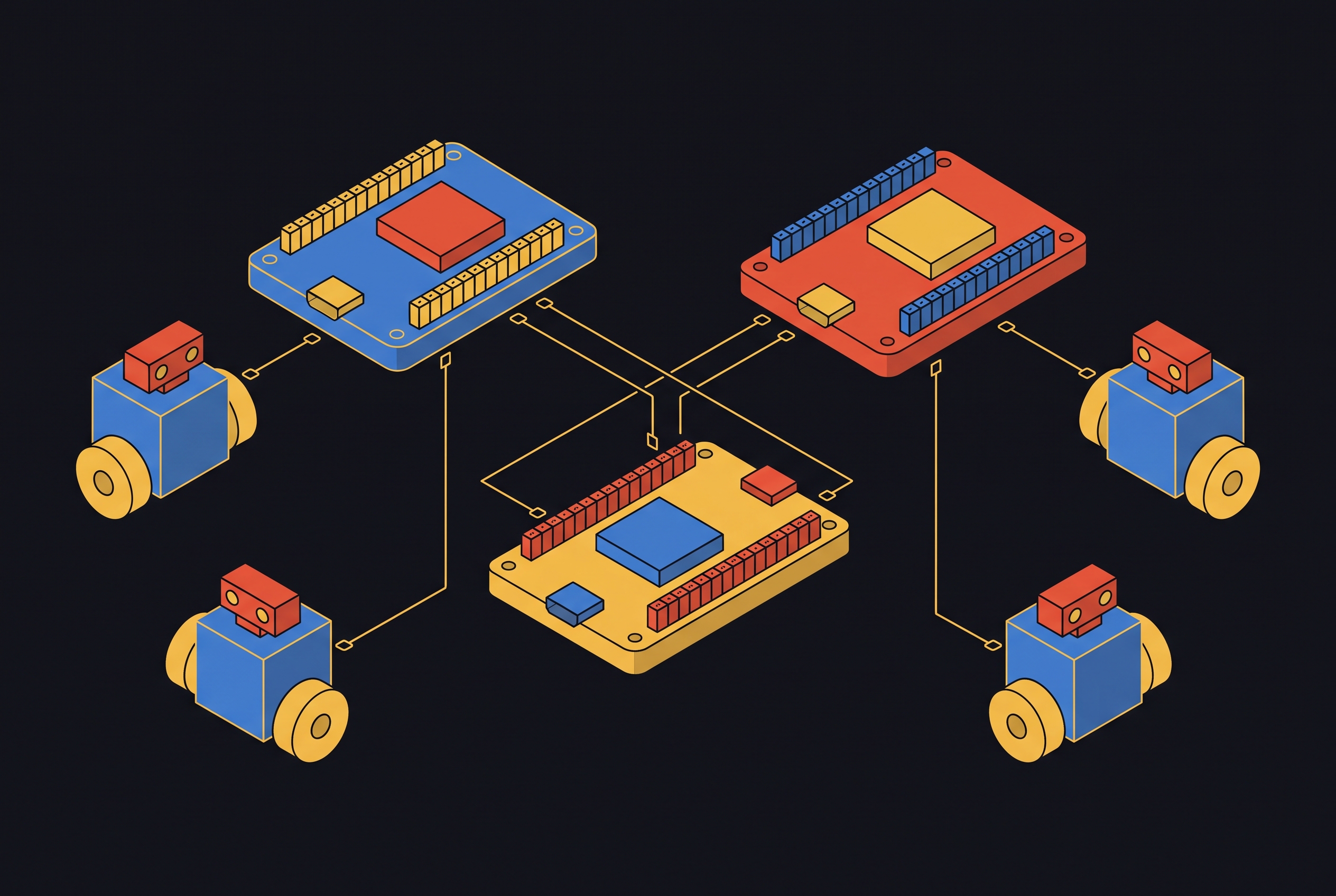
That concentration of responsibility becomes more pronounced as systems grow. When a robot is built around multiple microcontrollers, each handling a different subsystem, it typically routes all of them through one agent, so a single host process now holds the connectivity of every hardware node on the robot. That design runs against the distributed, fault-tolerant philosophy that ROS 2 was built around in the first place, where no single process is supposed to be a point of total failure for the rest of the graph. There's a cost on the data path as well: CDR serialization performed on the MCU adds latency to every message that crosses the client-agent boundary, and for high-frequency sensor streams that per-message cost accumulates into something real.
Practitioners discussing the architecture on the Open Robotics Discourse forum describe the agent as a particular source of friction in WiFi-connected and cloud-connected deployments, where the XRCE-DDS transport doesn't map cleanly onto wide-area networks or multi-hop topologies the way it does onto a simple wired or local wireless link. None of this makes the agent a design flaw to be avoided. For the large class of robots built around a single host and a wired or short-range wireless connection to their MCUs, the agent is dependable, and the overhead it introduces is manageable in practice. The liability sharpens when many MCUs sit behind one agent, or when network conditions stop matching what the agent assumes about connectivity.
How Zenoh opens a path to agent-less embedded nodes
The agent's structural limitations make Zenoh-based integration worth tracking closely, because Zenoh offers a path that removes the agent from the picture. The groundwork for that path was laid inside ROS 2 itself: with the Jazzy Jalisco release, rmw_zenoh arrived as an experimental, Tier-2 middleware alternative to DDS. It graduated to a first-class, Tier-1 option only with the subsequent Kilted Kaiju release, a sign of a technology moving from promising to production-supported over successive ROS 2 distributions.
The embedded counterpart to that shift is Zenoh-pico, a client built for constrained devices that can, in principle, take the place of the XRCE-DDS client running on an MCU today. Doing so would remove the host-side agent from the architecture entirely, giving the MCU something closer to an embedded RTPS participant that speaks directly into the Zenoh network rather than relying on an intermediary to represent it. At ROSConJP 2025, held on September 9, 2025, eSOL demonstrated robot operation built by applying micro-ROS concepts to Zenoh-pico directly. A subsequent software update extended that work with support for Zenoh and Zenoh-Pico version 1.4.0 running on M5Stack ESP32 development kits inside PlatformIO environments, and the demonstration showed the M5Stack boards communicating over both unicast and multicast without a traditional XRCE-DDS agent in the loop.
Community efforts are pushing on the same seam from a different angle. A project under ros-controls, zephyr-zenoh-integration, was proposed for a structured open-source mentorship program, was not selected, and is now continuing as an independent community effort to bring Zephyr RTOS microcontrollers into ros2_control as first-class participants over Zenoh. A working initial implementation already exists, but you still have to ask whether it is ready for production. A related firmware pattern, Pico-ROS running on Zephyr, replaces raw zenoh-pico publisher calls with a structured API and uses ROS 2 liveliness tokens so that a standard ros2 node list command shows the embedded board directly on the graph, with no host-side bridge standing between them. It is an early but concrete demonstration of what a fully agent-less, graph-transparent embedded node looks like in practice. What stands in the way of broader adoption is a more basic mismatch: Zenoh-pico's memory model does not yet align cleanly with the constraints hard RTOS targets impose, and that mismatch is the specific technical obstacle still unresolved between today's demonstrations and production deployment at scale.
Choosing a transport and RTOS for a micro-ROS deployment today
Choosing a transport and an RTOS for a micro-ROS deployment is not a matter of picking the newest option or the one with the most documentation. Each combination carries its own real-time profile, its own memory footprint, and its own degree of dependency on the agent, and the right combination follows from the application's latency budget, its network topology, and how much safety margin the system needs. UART or USB connections give you the lowest latency you can get in a single-host wired setup, they are the simplest option to debug when something goes wrong, and most tutorials still use them as the reference transport, including the standard STM32 getting-started path that most developers meet first. UDP over WiFi opens up wireless robots and multi-robot configurations that a wired transport simply cannot support, but it introduces latency variability that demands careful quality-of-service tuning, and it is the transport that exposes the agent's single-point-of-failure risk most acutely, since a dropped WiFi link severs every MCU node behind it at once. CAN or CAN FD suits automotive and industrial settings where multiple microcontrollers share a single bus, and its native priority arbitration lines up naturally with the real-time scheduling goals micro-ROS is built around. SPI and other custom transports round out the options: micro-ROS's transport abstraction layer accommodates them directly, and they become the right choice when the MCU and host share a single board and need low-overhead communication between tightly coupled components.
The RTOS choice follows the same logic: it favors maturity over novelty. FreeRTOS has the most mature micro-ROS integration available today, backed by the widest community support of any supported RTOS, and it remains the default choice for STM32-based projects. Developers working with ESP32 hardware are better served using the standalone ESP-IDF component, which integrates FreeRTOS directly rather than requiring a separate FreeRTOS layer bolted on afterward. None of these choices are made in isolation from the architectural trade-offs covered earlier: a transport that depends on a stable wired link tolerates the agent's single point of failure far better than a WiFi link does, and an RTOS chosen for its executor maturity matters more in a multi-chain system, where scheduling behavior under load sets whether the deployment meets its real-time deadlines or quietly misses them.
Sources
- Integrating ROS 2 with microcontrollers when using Zenoh - Embedded - Open Robotics Discourse
Confirmed the classic micro-ROS agent pattern and provided practitioner perspectives on WiFi transport limitations and single-point-of-failure risks.
- The Three Dimensions of ROS 2 Middleware
Provided the framing of temporal predictability as a structural requirement that strains ROS 2 middleware, cited in the opening section.
- Robot Operating System 2: Design, Architecture, and Uses In The Wild
Supplied the characterization of ROS 2 as a modular, distributed framework and its fault-tolerant design philosophy cited in multiple sections.
- Budget-based real-time Executor for Micro-ROS
Provided technical detail on the RCLC executor's scheduling strategy, priority inversion risks in multi-chain systems, and zero-dynamic-allocation configurations.
- micro-ROS Solutions
Provided details on the Renesas RA6M5-based Robot Body Controller deployment with micro-ROS in the OpenMANIPULATOR-X platform.
- Harness Engineering for Physical AI: Robot Middleware Is the Harness Layer
Described the robotic-assisted laparoscopic surgery deployment using an ESP32-S3 running micro-ROS for surgical toolhead feedback.