Hardware-in-the-Loop Testing With ROS 2 and Gazebo
Bridge ROS 2 software and real hardware through Gazebo simulation to catch integration failures.
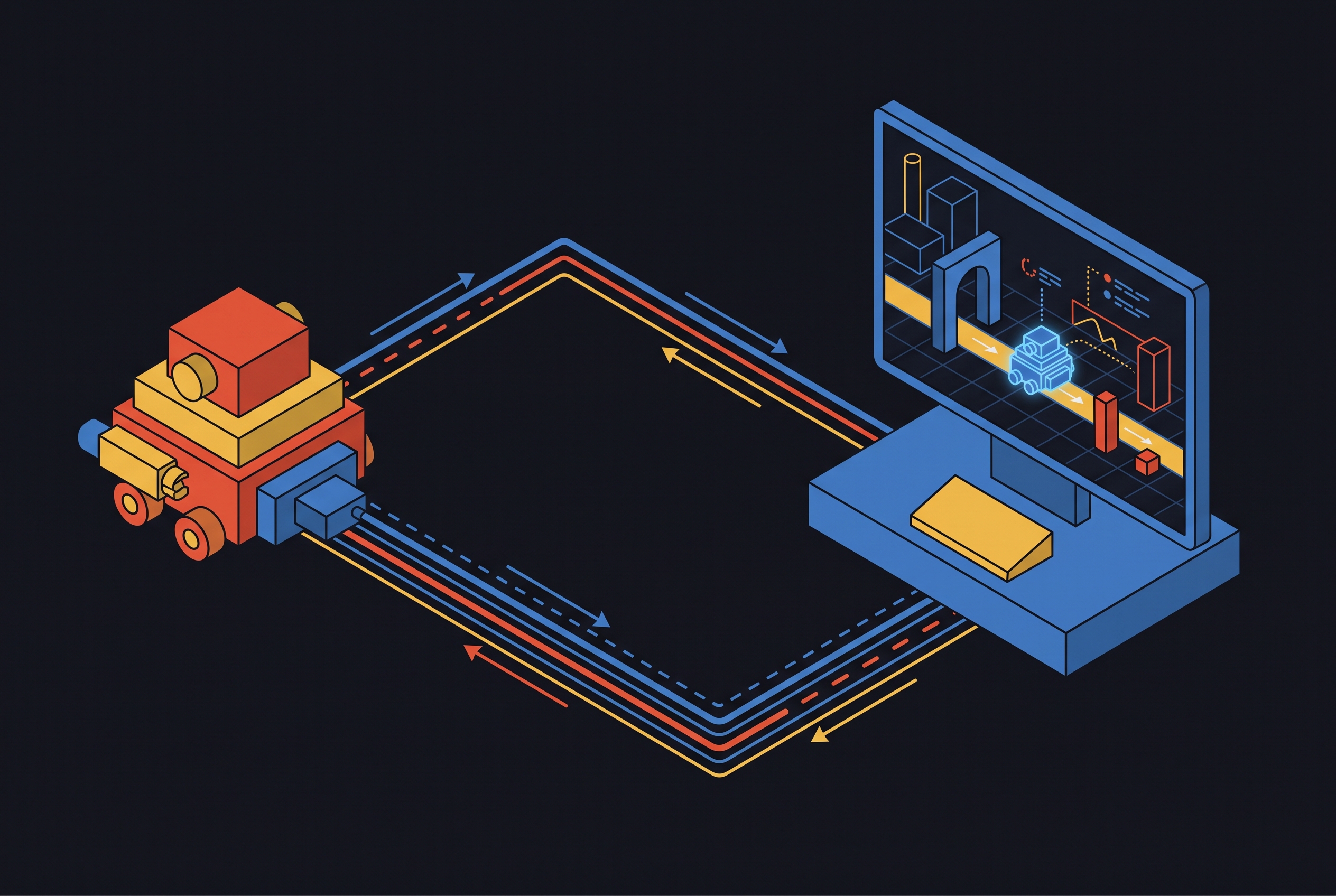
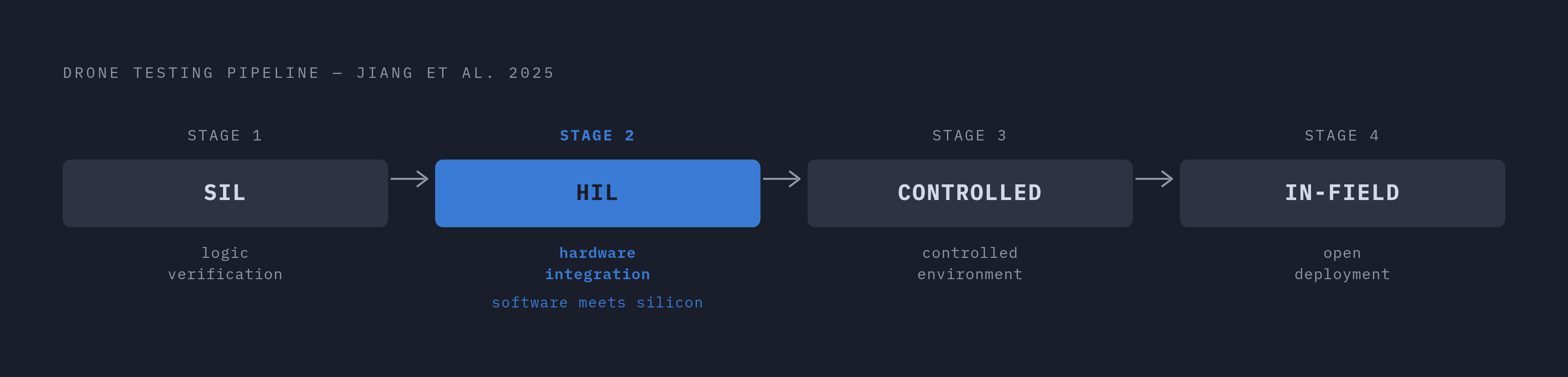
Hardware-in-the-loop testing exists to solve a specific problem: software simulation verifies logic, but it cannot verify integration. Software-in-the-loop (SIL) testing executes algorithms in isolation and confirms that they compute correctly. HIL puts real hardware into the feedback loop, so the system under test uses physical flight controllers, sensors, and actuators, not models of them. The drone testing pipeline formalized by Jiang et al. (2025) lays out four stages: SIL, HIL, controlled real-world testing, and in-field testing. HIL is stage two of four, the point where software meets hardware. Its purpose is to surface failure modes that a purely virtual stack cannot reproduce: hardware-software interface bugs, real-time latency constraints, sensor noise behavior, and actuator delay. None of these exist in a simulated process. They appear only when silicon and copper are in the loop.
How ROS 2 and Gazebo divide the work in a HIL setup
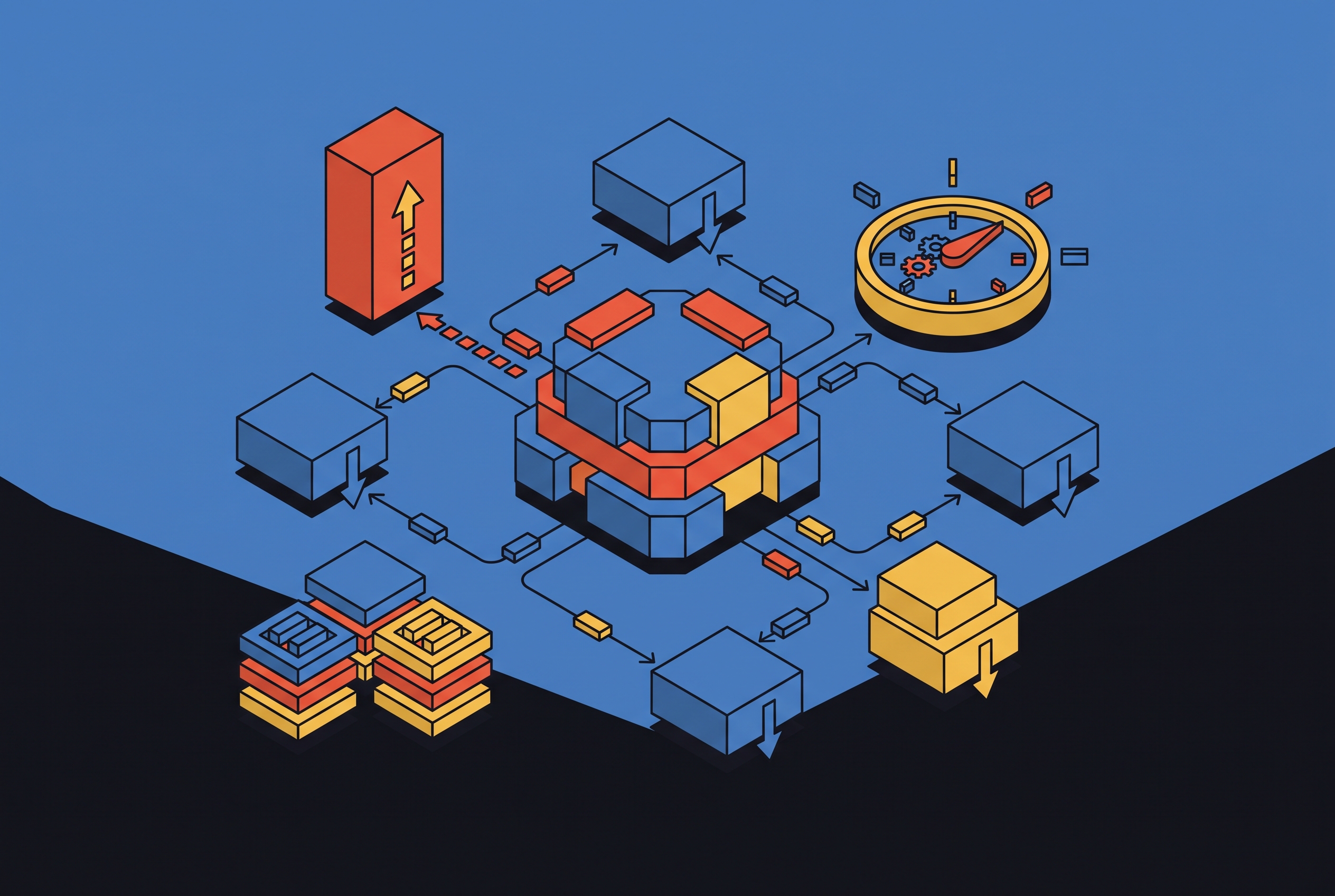
ROS 2 and Gazebo are not interchangeable parts of one system. Each owns a distinct layer, and HIL depends on both functioning correctly at their boundary. ROS 2 is middleware. It handles real-time messaging, modular software composition, and the bridge between hardware and simulation. Computational tasks such as perception, planning, control, and actuation are partitioned into discrete nodes that communicate through messages on defined topics, services, and actions. This partitioning means a team can swap a single node without redesigning the system, and nodes or groups of nodes can be tested in isolation. Gazebo's layer is different. It provides a high-fidelity, physics-based three-dimensional environment: rigid-body physics, sensor emulation for LiDAR, IMU, and cameras, and plugin-based extensibility for custom hardware or environmental effects. The boundary between these two layers is where HIL becomes possible. ROS 2 nodes connect to Gazebo through the ros_gz_bridge or an equivalent mechanism. Actuation commands, velocity and torque, flow from ROS 2 nodes into Gazebo. Sensor feedback flows back out. That bridge is what makes hardware-software-in-the-loop prototyping work.
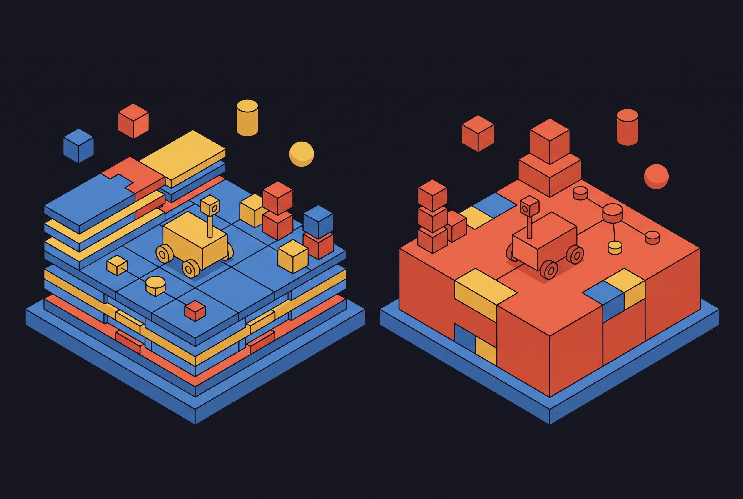
Robot models stay consistent across the boundary because they are described once, in URDF or XACRO, defining link and joint structures, inertial parameters, and sensor and actuator locations. The same descriptor runs in simulation and on the real platform. This modularity is what enables simple switching between simulated and real-world deployment. Every node above the bridge remains unchanged. Only what sits below the bridge, simulator or physical hardware, differs.
What "keeping hardware in the loop" concretely means for a drone
The signal flow becomes clear in a drone HIL setup. Normal PX4 firmware runs on real flight controller hardware, connected to Gazebo through USB or UART. Nothing about the autopilot is simulated. The bytes that leave the flight controller are the same bytes it would send in flight. Gazebo supplies the physics, sensors, and camera simulation. A µXRCE-DDS agent bridges the PX4 flight controller to the ROS 2 nodes above it, using the same code path as real hardware. That last point matters a great deal. The precision landing node, or any autonomy node above the autopilot, does not need to know whether it is talking to a simulator or a physical aircraft. The messages look identical. This architectural property, transparency across the boundary, is what gives HIL its value.
There is one site of failure that receives less attention than it should. The companion computer, the machine that runs the autonomy stack, often differs between simulation and deployment. A team may run one configuration of ROS 2 nodes and drivers in the lab and a different one on the aircraft. That gap is invisible until it breaks in the field. The mitigation is to build the autonomy stack image, containing ROS 2 nodes, autopilot interface middleware such as uXRCE-DDS or MAVROS, and perception pipelines, from the same Dockerfile for both simulation and deployment. The environment the code runs in becomes identical whether the test is HIL or real-world operation. The flight controller sees no difference. The autonomy stack sees no difference. Only the physics below changes.
Why the ROS 2 asynchronous execution model creates a reproducibility problem in HIL
ROS 2 is powerful because it is distributed and asynchronous. That same property creates a real engineering constraint. Callback execution order in a HIL loop cannot be guaranteed. Gazebo offers a lockstep mode that slows down physics to synchronize sensor and physics update rates, aligning all sensor outputs in time. But the remaining software outside Gazebo, the nodes receiving those messages and issuing commands, still runs on whatever schedule the executor chooses. Computation times and communication delays vary across hardware platforms, so deterministic callback execution cannot be achieved. These minor inconsistencies accumulate into divergent outcomes across runs. The problem is most consequential in continuous integration. A test suite that produces different results on different hardware cannot reliably catch regressions, because the passing or failing run may reflect scheduling rather than code quality.
The AutoRL multirotor attitude control research treats this problem directly. It proposes a ROS 2–Gazebo pipeline with deterministic, step-level coupling between control actions and physics updates, empirically verified across multiple rollouts with identical action sequences. The work exists specifically to address reproducibility gaps in learning-based flight control, where identical inputs must produce comparable training data. The constraint is real, but it is not fatal. Understanding it is what separates a functional HIL setup from a theoretical one.
How containerization and CI pipelines make HIL reproducible in practice
The operational answer to the reproducibility problem is containerization and automated CI, not a redesign of ROS 2's execution model. Containerized setups ensure cross-platform reproducibility by deploying the same containerized ROS 2 autonomy stack in simulation and on physical robots. The software environment is identical whether the test is HIL or deployment. The future directions published for ROS 2–Gazebo prototypes make this explicit: containerized deployments and seamless transitions from simulation to real-world testing are treated as the standard path, not an advanced refinement.
Teams have already demonstrated the pattern in competitive settings. OUXT Polaris, a maritime RobotX Challenge team, wired continuous integration into its development workflow. When a pull request was issued, a build test automatically ran once a day. If it failed, the pull request could not be merged, and the failure was sent immediately to a Slack channel. The loop was tight enough that a broken commit could not survive unnoticed. Fault injection extends the same automation to safety validation. Inside Gazebo, engineers intentionally kill a sensor node or simulate a motor failure and verify that safety controllers trigger correctly, whether that means an emergency stop or safe-mode recovery. The test is reproducible and automated. When a failure does occur, ros2 bag, rosbag2, enables data recording and replay, so debugging can happen after the fact without re-running the full hardware setup. The asynchronous execution model remains nondeterministic. The container and the CI pipeline make that nondeterminism manageable.
What Gazebo's physics and sensor simulation can and cannot cover
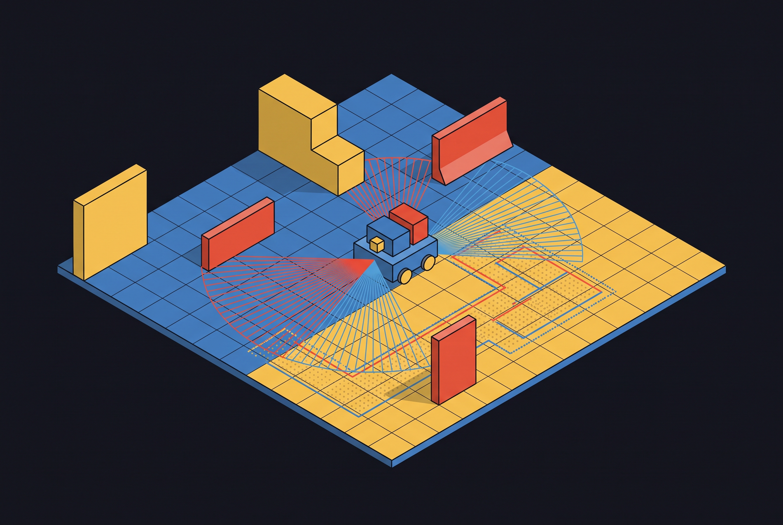
Gazebo's simulation capabilities cover the scenarios where HIL adds the most value, but there is a defined ceiling. What Gazebo handles well is substantial: rigid-body physics, sensor emulation for LiDAR, IMU, and cameras through plugins such as velodyne_gazebo_plugins, and multicamera plugins that model lens distortion and sun glare. Environmental interactions are faithful enough for algorithm validation and integration testing, which is precisely what HIL is for. What Gazebo cannot simulate is different in kind, not merely in fidelity. Mechanical wear, electromagnetic interference, and the specific behavior of a motor under load are outside its model. These require real hardware, and HIL provides that hardware. Recognizing this division of labor is part of designing a HIL setup that stays within what the simulation can actually support.
There are also ceilings that are practical rather than physical. Gazebo cannot maintain a good real-time factor above roughly twenty agents due to CPU usage. Multi-agent HIL at scale requires architectural choices beyond a single Gazebo instance, such as distributing simulation across multiple processes or accepting degraded real-time behavior. The sim-to-real gap for vision-based policies is subtler. Contact physics, visual appearance, and environmental dynamics all differ between a rendered scene and the world a camera actually sees. Policies learned in Gazebo can lose performance when transferred to real hardware. HIL reduces this gap, because the autonomy stack is running on real hardware and real firmware while training or evaluation happens, but it does not eliminate it. The rendering still comes from a computer.
When Gazebo is the wrong simulator and what teams choose instead
The bridge architecture in ROS 2 is simulator-agnostic enough that teams working at the edges of Gazebo's capabilities can swap in a domain-specific simulator without redesigning their autonomy stack. The clearest case is Brigham Young University's CougUV torpedo autonomous underwater vehicle. The team chose HoloOcean over Gazebo because acoustic-based sensors and control surfaces only function properly underwater, and Gazebo is limited in the realism of its simulation environments and in its perceptual sensing rendering capabilities. HoloOcean 2.0, built on the Unreal Engine 5.3 toolchain, provides high-fidelity torpedo AUV dynamics and advanced sonar simulation that Gazebo does not. The team paired HoloOcean with a new ROS 2 bridge and preserved the same HIL signal-flow pattern: simulated sensor data sent to the CougUV, control surface commands sent back to the simulator, vehicle dynamics calculated in the simulator. The architecture did not change. Only the simulator beneath the bridge did.
A field test at Bear Lake, UT in July 2025 validated the HIL results against real-world behavior. The HIL setup predicted field performance closely enough to reduce deployment risk, which is the metric that matters. The architectural lesson generalizes beyond AUVs. The ROS 2 bridge layer is what allows domain-specific simulators to slot into the same HIL pattern. The autonomy stack above the bridge does not change. Gazebo remains a well-supported default for ground and air vehicles. When a domain requires physics or sensing that Gazebo does not model, the bridge absorbs the substitution.
Gazebo Classic's discontinuation and what the current toolchain baseline looks like
Teams setting up HIL with ROS 2 and Gazebo in 2026 are working from a materially different baseline than most tutorials and older documentation describe. Gazebo Classic was discontinued in January 2025 and replaced with a restructured fork. Teams that do not know this may spend effort on setup that will not be maintainable. The current Gazebo uses an entity-component-system architecture, a modular physics plugin interface supporting DART, Bullet, and TPE, rendering through OGRE 2 with physically-based materials, and a library-based design where each capability is a separate library usable independently. The architecture is different enough that configuration knowledge from Gazebo Classic does not transfer cleanly.
The platform baseline changed as well. ROS 2 Lyrical Luth, the 2026 LTS release, brings a five-year support window, Gazebo Jetty as the officially recommended simulation pairing, a new executor, an asyncio-native Python model, a GPU buffer path, and rosbag2 improvements. For new, long-lived ROS 2 project, Lyrical Luth is the sensible default when the required hardware and packages support its Tier 1 baseline. The combination of Lyrical Luth with Gazebo Jetty is what a team starting now is actually working from.
How to wire a HIL setup: the practical configuration sequence
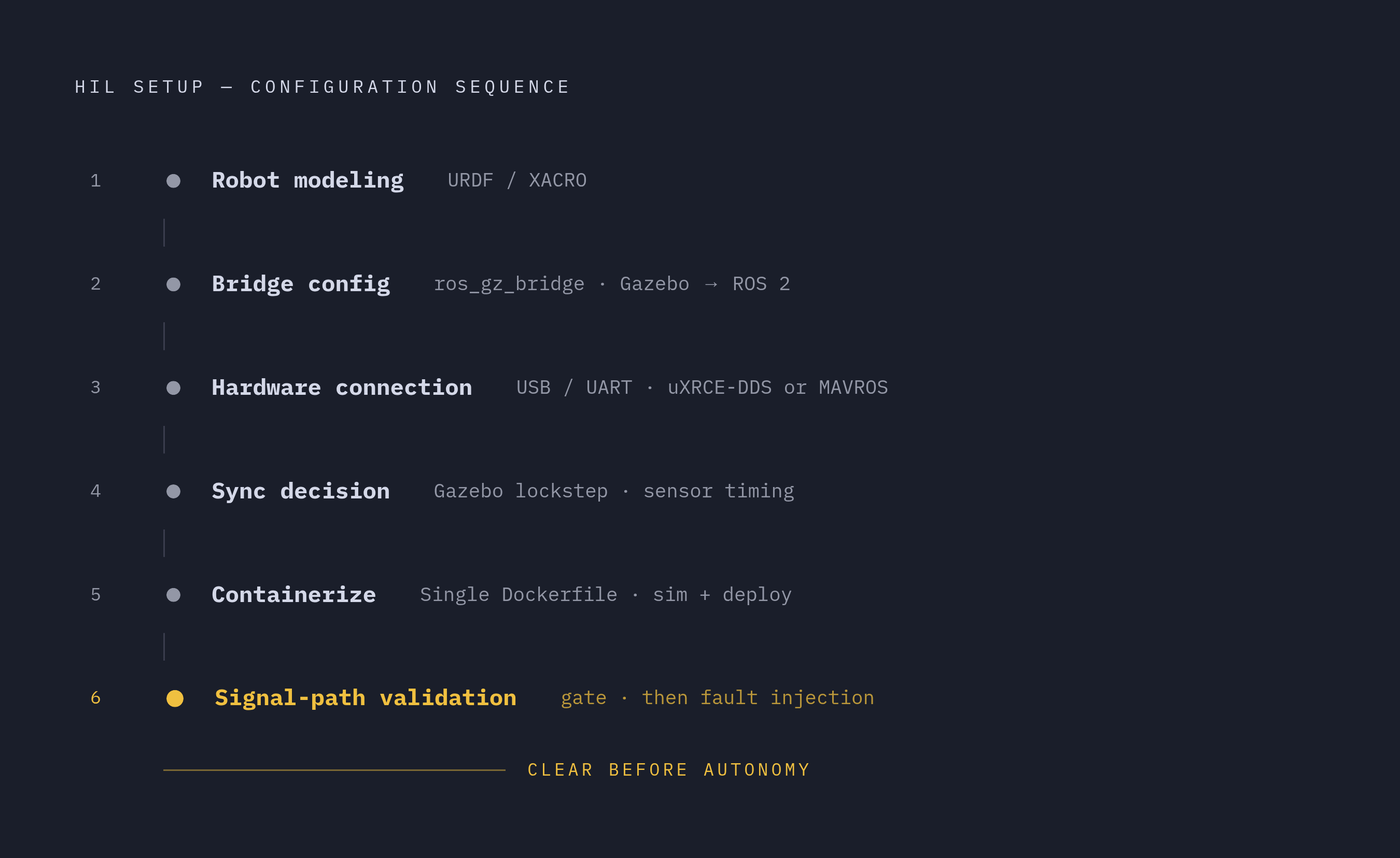
A working HIL configuration follows a definite sequence, and each step depends on the previous one being correct. The first step is robot modeling. Define the robot in URDF or XACRO with correct link and joint structures, inertial parameters, and sensor and actuator locations. The same descriptor runs in simulation and on real hardware. Step two is bridge configuration. Map Gazebo topics to ROS 2 topics through ros_gz_bridge: actuation commands, velocity and torque, flow from ROS 2 nodes into Gazebo, while sensor feedback for LiDAR, IMU, and cameras flows back out. Step three is real hardware connection. Connect the physical component, a flight controller via USB or UART, and configure the firmware interface middleware, uXRCE-DDS for PX4 or MAVROS for ArduPilot. Step four is synchronization. Decide whether to use Gazebo's lockstep mode for sensor output synchronization, while understanding that software execution order outside Gazebo remains uncontrolled. Lockstep aligns sensors. It does not make ROS 2 deterministic. Step five is containerizing the stack. Build the autonomy stack, autopilot interface middleware, and perception pipelines into a container image using the same Dockerfile for simulation and deployment.
Step six comes before any autonomy logic runs. Validate the signal path. Confirm that sensor data arrives at the hardware component and that commands return to the simulator. Only after that path is confirmed does mission logic get introduced. Fault injection follows as a validation step. Kill a sensor node, simulate a motor failure, and verify that safety controllers respond correctly. A setup that passes its signal-path validation and fault-injection tests is ready to carry autonomy software. A setup that skips these steps will fail in ways that are hard to attribute after the fact.
What HIL with ROS 2 and Gazebo reliably validates and where field testing remains necessary
HIL with ROS 2 and Gazebo validates what it is designed to validate. Hardware-software interface correctness, system latency and real-time performance constraints, sensor-to-actuator signal paths, safety controller responses to injected faults, and behavior consistency across software versions via CI. These are exactly the integration failures that field testing is too slow and too expensive to catch. What HIL does not replace is equally definable. Mechanical wear behavior, electromagnetic interference, motor behavior under real load, and the visual and physical discrepancies between a rendered environment and the real world that affect vision-based policies. These remain outside what any simulator can model. The CougUV field trial at Bear Lake in July 2025 illustrates the correct sequence: HIL in the lab first, field trial second, with HIL results compared against real-world performance to measure the remaining sim-to-real gap. The comparison is what tells a team how much it can trust its simulation.
The full pipeline remains four stages: SIL, HIL, controlled real-world testing, in-field testing. HIL is not the final gate. It is the stage where hardware and software learn to work together, before the cost of discovering that they cannot is paid at a test range or in open water. A HIL setup that catches integration failures before field trials reduces the cost and risk of those trials. It does not eliminate them, and honest planning never pretends otherwise. What it does is make each field deployment more targeted, more likely to succeed, and less likely to return with a failure that a lab bench could have caught. That is the toolchain's purpose.
Sources
- ROS2/Gazebo Prototype: Cyber-Physical Simulation
Provided details on containerized ROS 2–Gazebo deployments, real-time factor limits with multiple agents, and the CI/simulation-to-real-world transition practices described in the article.
- Testing and Evaluation of Underwater Vehicle Using Hardware-In-The-Loop Simulation with HoloOcean
Supplied information on the CougUV AUV HIL setup using HoloOcean 2.0 with Unreal Engine 5.3, including the Bear Lake field trial and its sim-to-real gap comparison.
- Testing and Evaluation of Underwater Vehicle Using Hardware-In-The-Loop Simulation with HoloOcean
Source for the CougUV torpedo AUV HIL evaluation with HoloOcean and the Bear Lake field trial results cited in the article's closing section.
- A Step-by-Step Guide to Creating a Robust Autonomous Drone Testing Pipeline
Provided the four-stage drone testing pipeline (SIL, HIL, controlled real-world, in-field) formalized by Jiang et al. that structures the article's framing of HIL's role.
- Robot Testing & Simulation QA — Gazebo, Isaac Sim & Hardware-in-Loop
Provided practical HIL workflow details including Gazebo fault injection, ros2 bag for replay, OUXT Polaris CI integration, and containerized stack practices described in the article.
- ROS-Compatible Robotics Simulators for Industry 4.0 and Industry 5.0: A Systematic Review of Trends and Technologies
Supplied the systematic review of ROS-compatible simulators informing the article's discussion of Gazebo's sensor plugins, URDF/XACRO modeling, and the ros_gz_bridge architecture.