Camera Calibration Pipelines for Robot Vision Systems
Precise camera calibration ensures robots can act on what they see, not just recognize it.
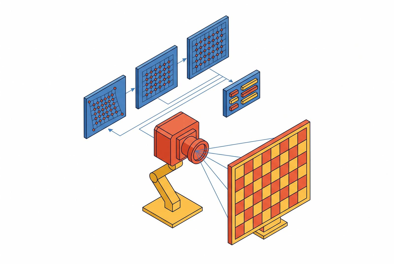
Camera Calibration Pipelines for Robot Vision Systems.
Geometric accuracy as the foundation of robot vision
A robot that can identify an object is not the same as a robot that knows where that object sits in physical space, and camera calibration is the discipline that closes that gap. Pattern recognition tells a system what it's looking at; metric accuracy tells it how far away that thing is, at what angle, and with what margin of error, which is the information a robot arm or a mobile platform actually needs to act. An uncalibrated camera doesn't announce its own errors. It hands off warped geometry as if it were ground truth, and every downstream stage, from depth estimation to grasp planning, inherits that distortion without any signal that something is wrong.
That silence is what makes calibration a foundation rather than a cleanup step tacked onto the front of a pipeline. A distortion error baked into the intrinsic model appears not as noise that averages out, but as a consistent bias. A distortion error baked into the intrinsic model is visible as a consistent bias, and a consistent bias in a robot's spatial reasoning is often worse than random noise, because it's confident and wrong in the same direction every time. Sub-pixel edge detection paired with a properly calibrated camera can hit measurement accuracy in the tens of micrometers under controlled conditions, which gives a sense of what the ceiling looks like when the geometry is actually right.
Robotic systems rarely rely on vision alone, either. Laser trackers used in precision robot positioning reach distance measurement precision around 10 micrometers per meter, and that figure matters less as a laser tracker spec and more as a benchmark: whatever role the camera plays alongside that tracker, its calibration has to hold up to a comparable standard of precision, or it becomes the weak link in a chain that's only as accurate as its worst-calibrated sensor https://arxiv.org/pdf/2603.15126.
The parameter space a calibration pipeline must recover
Every calibration pipeline is solving for a specific, well-defined set of unknowns, and naming them directly is better than treating calibration as a black box. The principal point marks where the optical axis actually punches through the sensor plane, and if that point is miscalibrated, the result is a spatial offset that appears consistently across the whole image rather than something random. Skew sits in the matrix too, and in nearly every modern sensor it's close enough to zero to ignore in practice, though it stays in the model because the structure of the math requires it.
None of that touches distortion, which is a separate problem the camera matrix alone can't describe. Radial distortion, captured by coefficients often labeled k1, k2, and k3, bends straight lines into curves, and the effect gets worse the farther out toward the edges of the frame you look. Tangential distortion, described by p1 and p2, comes from the lens not sitting perfectly parallel to the sensor, a physical misalignment baked into the hardware. Wide-angle and fisheye lenses push past what these polynomial terms can handle at all, which is why models like the Double Sphere model exist, built specifically for catadioptric and fisheye optics where the standard radial-tangential approach breaks down.
Extrinsic parameters are the third piece, and they're what tie the camera to the world outside it rather than to its own internal optics. A rotation matrix and a translation vector describe the rigid-body transform from world coordinates into camera coordinates; getting the translation wrong causes distance errors, while getting the rotation wrong misaligns depth across a multi-camera rig in a way that's much harder to diagnose after the fact. Stripped to one line, the process reads: a world point gets multiplied through K and the [R|t] transform to land at an image point. Calibration recovers the unknowns inside that chain. Intrinsic parameters describe what lives inside the camera matrix K (3×3). In a ROS/TF2 robot stack, a calibrated transform tree allows projection of any 3D point into the image plane.
Calibration target selection and the guidance each target gives the solver
Picking a calibration target is not a cosmetic decision, it changes what the solver can and can't see. The classical checkerboard remains the baseline against which everything else gets measured, because it compares where a grid corner should sit in object space against where it actually lands in the image. Checkerboard corners have a real advantage over circle grids here: they stay invariant to distortion bias, whereas circle-based targets pick up perspective and distortion errors that corrupt the very measurement they're supposed to provide. Active targets, digital displays rather than printed boards, can push reprojection error even lower than a printed checkerboard, but that comes at a cost: glass refraction has to be compensated for, and the setup needs a tripod, so the precision gain trades against a more demanding rig.
ArUco boards take a different approach, using unique binary-pattern markers that survive partial occlusion in a way a plain checkerboard can't. The tradeoff is that each marker only contributes four corner points to the solver, versus the dense grid a checkerboard offers.
That's the deciding factor for any setup with cameras mounted at close to perpendicular angles to each other, where no single frame captures the whole board. It's become the standard choice for intrinsic calibration on legged robots, where an operator physically walks the AprilGrid through each camera's field of view until coverage across the image plane is sufficient. In underwater trials, AprilTag detected more reliably than both ARToolKit and ArUco, though at the cost of heavier computation, a tradeoff that matters when the calibration runs onboard a submersible with limited processing headroom rather than on a bench.
ChArUco boards try to take the best of both worlds by embedding ArUco markers inside the white squares of a chessboard pattern, using the marker detections to interpolate the positions of the chessboard corners. The interpolated corners keep the sub-pixel accuracy that makes checkerboards attractive, while inheriting the occlusion robustness that comes from ArUco's marker IDs. Such an approach offers a computational advantage, proving more efficient than AprilTags on limited hardware such as mobile devices. Experimental evidence shows lower translation and rotation errors than ArUco-only, making it preferred when accurate camera-to-robot-arm spatial transformation is required.
Hand-eye calibration: connecting camera measurements to robot workspace coordinates
Hand-eye calibration answers a specific and unavoidable question: once a camera has measured something, how does that measurement translate into coordinates the robot's controller actually understands? Get this transform wrong and it doesn't matter how sharp the intrinsic and distortion correction is upstream, because the robot will still reach for the wrong point in space.
The problem splits into two configurations, and each demands its own mathematical formulation. Eye-in-hand setups mount the camera directly on the robot's end-effector, and the classic formulation there is the AX = XB matrix equation. Eye-to-hand setups fix the camera in place, watching the robot move through its workspace instead, which changes the math to AX = YB. Many of the classical solvers built for one configuration simply don't transfer to the other, which is part of why newer research has pushed toward methods flexible enough to handle both without requiring a separate derivation for each.
The traditional pipeline carries a practical weakness beyond the math: it's slow to run, prone to operator error, and worse, it assumes the camera-to-robot relationship stays fixed over time. That assumption doesn't hold in the field. A mount that passes calibration on day one can drift as vibration, thermal cycling, or an accidental bump shifts the camera relative to the robot base, and a pipeline with no way to detect or correct for that drift will keep reporting confident numbers that are quietly wrong.
Recent learning-based approaches have started closing that gap on raw accuracy. One learning-based 3D vision hand-eye calibration method reported a translation deviation of 0.930 mm and a rotation deviation of 0.265 degrees, with separate 3D reconstruction experiments from the same line of work showing a rotation error of 0.994 degrees and a position error of 1.697 mm https://link.springer.com/content/pdf/10.1007/s10846-024-02166-4.pdf. Numbers in that range put camera-based hand-eye calibration within striking distance of dedicated metrology hardware, at a fraction of the cost and setup time.
Mobile ground robots present a geometry that breaks most of the standard playbook. At KIT Karlsruhe, researchers working on a mobile ground robot developed a specialized hand-eye calibration approach. The solution paired a referencing plate that combines laser-tracker reflector nests with a standard camera calibration target: the robot moves to two separate positions, the laser tracker measures both the platform and the plate's reflector positions at each, and that data lets the solver compute the robot-camera transform directly. The result reached sub-millimeter repeatability, a level of precision that matches what the laser tracker itself is capable of and gives the camera pipeline no reason to be the weak link in that particular system.
Multi-sensor calibration chains: how camera, LiDAR, and IMU parameters depend on each other
Fusing camera, LiDAR, and IMU data has become standard practice across autonomous vehicles and robotics, but the field hasn't caught up to that adoption with a settled methodology. A review in PMC makes this explicit, pointing out the lack of systematic comparative analysis across the different sensor combination approaches in use, which is a polite way of saying the field has plenty of working systems and not much consensus on which calibration strategy is actually best for a given sensor mix https://pmc.ncbi.nlm.nih.gov/articles/PMC12431046/.
Camera-IMU calibration carries its own layer of complexity, because it has to solve for spatial alignment and temporal alignment at once. The Kalibr toolbox, developed at ETH Zurich, has become the dominant open-source tool for this, solving multi-camera intrinsics and extrinsics together with the spatial and temporal calibration of an IMU, including the time offset between when the IMU and the camera actually report an event. That's not a niche academic tool: Intel RealSense D435i cameras get calibrated with Kalibr in practical deployments for exactly this, stereo intrinsics and extrinsics alongside IMU spatial-temporal alignment. Kalibr has a real cost, though. Even working from an ideal dataset, it demands significant computational time to converge, and any attempt to run calibration online, rather than as an offline batch process, runs into accuracy that's sensitive to lighting changes, occlusion, and anything moving in the scene.
The GrandTour legged-robot dataset shows what a full multi-sensor calibration chain looks like when it's done end to end. The pipeline starts by calibrating ten cameras into a single, metrically consistent bundle, and only after that bundle is locked down does it get used to anchor every subsequent joint calibration involving prisms, LiDARs, and IMUs. For the IMUs specifically, the process runs an Allan variance analysis to characterize IMU intrinsics first, then hands off to Kalibr to solve for the extrinsics of every IMU relative to the front-facing global shutter cameras. For LiDAR-to-camera alignment, the pipeline uses DiffCal, an intensity-alignment method that can work from partial views of the target inside the LiDAR point cloud, which makes it considerably more data-efficient than plane-based calibration approaches that need many observations from a wide spread of orientations to converge.
The sequencing here isn't incidental, it's load-bearing. The camera bundle has to be metrically correct before anything else can be anchored to it, because an error introduced at that first stage doesn't stay contained. It propagates outward into every LiDAR and IMU relationship built on top of it. The entire multi-sensor chain is only as trustworthy as the camera calibration sitting at its root.
Rigs where cameras don't all share the same field of view add a further wrinkle. Kalibr is built to explicitly support setups without a globally shared overlapping field of view, and this is exactly the situation where AprilGrid's per-marker IDs earn their keep, since they let calibration proceed even when no single frame captures the whole target. A newer line of research is trying to remove the target from this equation entirely: implicit multi-camera calibration using Gaussian processes, by De Boi, Ribbens, Golanova, Kapov, and Verspeek, published in Machine Vision and Applications on 11 September 2026, represents an emerging non-target-based approach to calibrating cameras whose fields of view only partially overlap.
LiDAR-camera extrinsic calibration in the field: target-based accuracy versus targetless deployability
Target-based calibration for a multi-sensor pair, using checkerboards or custom-built boards, delivers strong accuracy under lab conditions, but that accuracy comes bundled with constraints that don't survive contact with the field. The board has to be installed precisely, and the capture setup has to be tightly controlled, which is workable on a bench and close to impossible across a large outdoor driving environment where you can't just walk a checkerboard out in front of every sensor pair whenever alignment needs checking.
That constraint would matter less if extrinsic parameters just stayed fixed once calibrated, but they don't. Vibration and the general wear of operating a vehicle or a robot in the real world cause the extrinsics between that sensor pair to drift over time, and re-running a full target-based procedure out in the field is, in most operational settings, simply not an option.
Targetless calibration methods are the direct response to that gap, and two approaches published in 2026 illustrate where the research is heading. One, from Chen and Sun in Frontiers in Robotics and AI in March 2026, works by minimizing what the authors call a semantic distribution consistency risk on SE(3), aligning semantic probability distributions extracted from the camera and the LiDAR directly in the image domain, with no physical target involved at all. The other, from Jeong and colleagues in Sensors in February 2026, takes a different route, aligning structural boundaries that each sensor detects independently of the other, without relying on any object-class assumptions.
Both approaches share the same underlying weakness: targetless calibration means optimizing a highly non-convex objective, and that optimization loses robustness in cluttered or unpredictable outdoor scenes in a way a controlled checkerboard setup never has to contend with. The tradeoff between target-based accuracy and targetless deployability isn't close to resolved, it's just being worked on from both directions at once.
The same targetless logic is starting to extend past that original sensor pairing entirely. Online radar-camera calibration, described in a paper published in Scientific Reports by Cao, Zhu, Gu, Xi, Wang, Luo, and Feng titled "Fusion calib: azimuth angle and multi frame tracking for online extrinsic radar-camera calibration," uses azimuth angle estimation combined with multi-frame tracking to solve extrinsic calibration between radar and camera without a target, extending the targetless principle to a different sensor modality. It's a signal that the targetless approach isn't a one-off fix for that particular sensor pairing specifically, but a direction the broader sensor-fusion field is converging on as sensor suites keep getting more heterogeneous and harder to calibrate by hand.